Use of a More Recent Browser is Recommended
This site uses modern HTML5 features and may not render correctly on earlier browsers. If you use Internet Explorer, version 11 and later is recommended.


One of the capabilities that is missing from the Amazon Echo is the ability to initiate spoken notifications even when the user hasn't addressed the Echo. Although Amazon will likely address this at some ... [More]
Projects Raspberry Pi Software Home Automation
I noticed Rich Hawkes project on Hackaday for a WS2812 LED Tree and then reading comments further found a lasercut tree on Hackaday.io. The 7 rings were a little pricey but I found this 93 LED 5-ring set ... [More]
Projects Raspberry Pi Software
Quite a while back at one of our meetup groups one of the attendees wanted a way to monitor and document sound levels. We discussed a couple of approaches. One would be to use a microphone and monitor ... [More]
Projects Raspberry Pi Software
Over the last few years, we've had fun planning and designing birthday cakes for our daughter. As her next birthday is coming up soon and we're in the planning/design process once again, I thought I'd ... [More]
Misc
A couple of years back my daughter picked a science project that involved growing beans in varying magnetic fields. I thought it might be interesting to film the beans growing over a period of weeks. An ... [More]
Projects Raspberry Pi Software
The Amazon Echo can be extremely useful for triggering home automation. This ranges from custom homebrew devices to widely used devices like Insteon, Wink, etc. I happen to have a mixture of devices including ... [More]
Projects Raspberry Pi Software Home Automation
When they were first introduced, I ordered a couple of Adafruit’s NeoPixel Rings that have 16 RGB LEDs in a 1.75″ diameter ring. I hadn’t decided exactly how I was going to use them but when I saw Phil ... [More]
Arduino Halloween Projects
At our daughter's school, all the 2nd graders put together a "state board" project. They are randomly assigned a state (in our daughter's case, Vermont) and the students work to put together a poster on ... [More]
Projects Raspberry Pi Software
I was inspired by Phil Burgess' great electronic mask project and knew I had to build one of my own. The project is detailed in a combination of Adafruit tutorials on Animating Multiple LED Backpacks ... [More]
Arduino Halloween Projects
In my last post, I explored alarm monitoring using the Raspberry Pi and Arduino. I thought I'd give the Electric Imp a try as well. The Electric Imp is a WiFi module and Cortex-M3 processor built into ... [More]
Arduino Home Automation Projects Software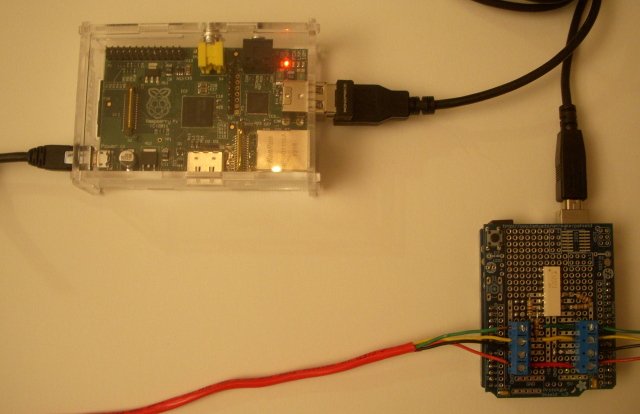
I spotted a post by Lior Hass on Hackaday a little while back where he described his Alarmino project where his alarm system now connects with an Arduino and a custom board to simulate the phone line and interpret Contact-ID ... [More]
Arduino Home Automation Projects Raspberry Pi Software
I wanted to control my Romo (the cellbot from Romotive) from my PC. But I like Romotive's control app and didn't really want to write my own at this point using their SDK. Instead, I just wanted to control ... [More]
Robots Software
I was reading the April 2012 issue of Elektor and spotted an article by Ludovic Mézière on building a Thermometer using Giant Gottlieb® Displays. I was really intrigued by his use of large mechanical ... [More]
Arduino Projects
A couple weeks back I got Romotive's Romo cell bot from a project I sponsored on Kickstarter. Cell bots use an onboard cellphone as their controller. As with other cell bots I've built, audio out is used ... [More]
Kickstarter Projects Robots
I was playing a game of Connect4 with my daughter one day and it occurred to me there might be a nice way of sensing the moves in the physical game in order to introduce a computer player. Looking at the ... [More]
Arduino Projects
I happen to have some old 12 inch optical disks made of glass. So when I saw Terry and Adam Clarkson's ClockOS project on Kickstarter, I recognized the potential for an awesome clock!The ClockOS board ... [More]
Arduino Kickstarter Projects
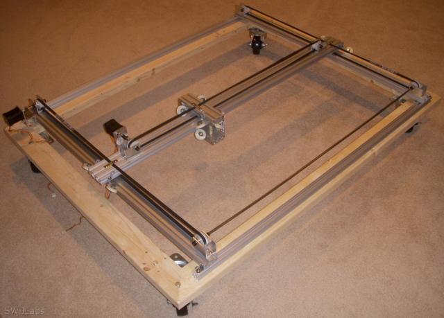
I first saw the EggBot in action at MakerFaire and then waited to get in the queue to get one as Evil Mad Science prepared the kit for sale (just as I await their Digi-Comp II now). As I was just getting ... [More]
Misc Kits Projects Robots
A few months back, I enjoyed assembling the Gakken Karakuri Somersault Doll (I got mine online from the Maker Shed). What's amazing about the doll is that it slowly completes a series of backward somersaults ... [More]
Gakken Kits Robots
While walking around Akihabara in Tokyo, we stumbled across a robot competition. This was totally unplanned on our part but it turned out to be a Kondo Robotics humanoid robot competition. The small ... [More]
Robots Trips
While visiting Tokyo, I spent some time in Akihabara where I stopped at the vStone Robot Store. I spotted a new balancing bot they had called the Beauto Balancer Duo (Reseller with English translation) ... [More]
Robots Trips
I first saw Pololu's 3pi robot in action at MakerFaire 2009. It was an impressive and agile line follower with a well-designed compact body. I brought one home and came to realize that it was even quicker ... [More]
Arduino Robots
The Secret Knock Gumball Machine is a project I built from the plans and instructions from Steve Hoefer's article in Make magazine (volume 25). Gumballs are dispensed only to those who use the secret knock ... [More]
Arduino Make Magazine Project Projects
I met the Macetech guys at Makerfaire 2009 in San Mateo and picked up a number of ShiftBrites. This was my first of several multi-RGB LED projects. I decided to array the 16 Shift Brites I had into a ... [More]
Arduino Projects
I thought I'd share another project from a few years back. Back in late 2007 I just finished up my third DARPA Grand Challenge Event (as an author of the pre-event simulator and real-time tracking software ... [More]
Projects Robots
For Halloween 2009 my daughter got a butterfly princess costume. We thought it might be nice to light it up for safety and a nice effect. I thought of EL wire, which I'd just discovered and bought some ... [More]
Halloween Projects
After attending Adrian Crenshaw's talk at DefCon18 (slides, video) on using the Teensy as an exploit tool, I was inspired to give it a try. I took a Teensy and added an RGB LED, photo sensor, DIP switches, ... [More]
Arduino Projects
In order to monitor our power consumption at our house, I set out to install a TED (The Energy Detective) system. The system monitors current flow into the house using inductive taps. In our case, we ... [More]
Home Automation Projects
The Tweet-a-Watt was one of the first projects I built from an article in Make magazine. I've since built many more. It also introduced me to Limor Fried and her company Adafruit. It turns out I already ... [More]
Home Automation Make Magazine Project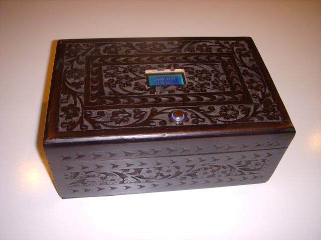
I was intrigued by Mikal's article on his Reverse Geocache Puzzle Box from Make issue 25. This is a box which will open only in a very specific place (as determined by its internal GPS system). The LCD ... [More]
Arduino Make Magazine Project Projects
While I was in Japan I was able to visit one of the leading science museums in Tokyo -- the Miraikan. I recognized a few of the exhibits as things I'd seen described in blogs over the years -- like the ... [More]
Trips
I've enjoyed assembling Gakken kits for some time. Ever since I had seen videos of Theo Jansen's work, I'd wanted to build models of his work. Then I heard about the Gakken kit but it wasn't yet imported ... [More]
Gakken Kits Projects
My daughter wanted to dress as Hermione Granger for the Halloween party at her school. We thought we'd jazz it up a bit with a special book she could hold -- one which might play the Harry Potter theme ... [More]
Arduino Halloween Projects
There is a wonderful museum which exhibits working automata of the Edo era in Japan. It's called Shishi Kaikan and it's located in Takayama, Japan. The automata are mechanical marvels. A couple of these ... [More]
Robots Trips
In December I received and mounted the Moore Pattern Kinetic Sculpture that Jeff Lieberman designed (from a KickStarter sponsorship). Although the motor is very quiet, I used an X10 module and motion sensor ... [More]
Art Home Automation Kickstarter